
Custom Humanoid Actuator Duty Cycle Testing
Screen RMS torque and thermal headroom. Prepare a duty cycle bench test brief.
Duty Cycle Screening Tool
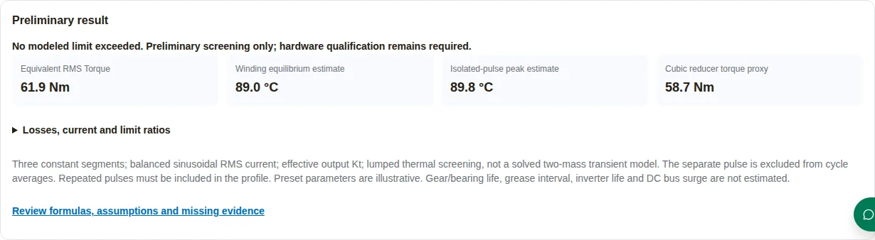
Preliminary result
- Equivalent RMS Torque
- 61.9 Nm
- Winding equilibrium estimate
- 89.0 °C
- Isolated-pulse peak estimate
- 89.8 °C
- Cubic reducer torque proxy
- 58.7 Nm
Losses, current and limit ratios
Cycle: 1.40 s; RMS line current: 21.73 A; continuous torque utilization: 82.6%; repeated-peak reducer utilization: 81.8%; mean motor speed: 2802 rpm.
Copper at 20°C: 85.0 W, hot copper: 108.1 W; total heat: 123.1 W; mean thermal margin: 46.0 °C, incremental isolated-pulse rise: 0.8 °C.
Three constant segments; balanced sinusoidal RMS current; effective output Kt; lumped thermal screening, not a solved two-mass transient model. The separate pulse is excluded from cycle averages. Repeated pulses must be included in the profile. Preset parameters are illustrative. Gear/bearing life, grease interval, inverter life and DC bus surge are not estimated.
Review formulas, assumptions and missing evidenceNext steps for this result
- Represent every repeated pulse in the cycle trace; the separate pulse field checks an isolated event only. Three constant segments omit within-segment ripple.
- Next: export this preliminary brief and verify signed torque/speed, phase current and winding temperatures on an instrumented dynamometer.
1. What to decide before a duty cycle test
Use this page to prepare a bench protocol, not to approve a joint for deployment. Thermal, transmission and electronics limits are separate constraints. A satisfactory RMS load alone cannot close all three.
| Decision | What this page supplies | What closes the gap |
|---|---|---|
| Screen current heating | RMS load, effective Kt and copper-loss calculation | Measured current and motor-specific overload protection; see maxon below |
| Check transmission loading | Cubic average proxy and entered repeated-peak limit | Selected reducer method, speed limits and pulse-frequency approval; see manufacturer references |
| Plan lubrication validation | Test conditions and unknowns | Grease supplier temperature, fill and oscillation guidance; oil separation alone is insufficient |
| Establish service life | Reliability planning checklist | Samples, failures, censoring and confidence model; see NIST below |
Evidence: motor overload method, reducer rating definitions, oil-separation scope and reliability confidence bounds. These support the distinctions, not the example input values.
2. Define the complete signed load profile
Capture torque, speed, phase current and timestamps from the intended task. Include stance, return, dwell, payload changes and braking. The tool approximates three constant segments. An average torque is not a substitute for RMS when current varies inside a segment. All durations are positive; torque and speed may be negative.
| Input | Preparation | Failure if omitted |
|---|---|---|
| Segment torque | Constant value, or current-equivalent RMS magnitude with direction recorded separately | A signed mean can cancel heating pulses |
| Segment speed | Use direction and rotation-weighted duration | Unsigned data loses braking direction |
| Repeating pulse | Include in the sampled cycle integral; merge segments only if the relevant moments are preserved | Separate isolated-pulse field does not update average losses |
| Dwell | Record holding current at zero speed | Stationary joints can still heat and fret |
3. Reproduce the calculation and its boundaries
The interactive model uses these equations. It is an analytical screening approximation. The thermal network diagram shows the richer two-node characterization needed for hardware correlation; the tool does not solve that network in time.
| Quantity | Calculation | Boundary |
|---|---|---|
| RMS torque / line current | T_RMS = √(ΣTi²ti / Σti); I_RMS = T_RMS / Kt | Kt is effective output Nm per line RMS ampere, assumed constant |
| Copper loss at 20°C | P20 = 1.5 × I_RMS² × R_LL | Balanced sinusoidal three-phase current, terminal DC line-to-line resistance; harmonics omitted |
| Copper temperature feedback | R(Tw) = R20[1 + 0.00393(Tw − 20)] | Linear copper coefficient; cooling path and other heat assumed constant |
| Equilibrium | Tw = [Tamb + Rth(P20(1 − 20α) + Pother)] / [1 − P20αRth] | Denominator ≤ 0.02 or Tw > 300°C: temperature withheld; 300°C is a model cutoff, never an operating allowance |
| Isolated pulse rise | ΔTw = max(0, Ppeak − Phot) × Rw × (1 − exp(−tpulse/τw)) | Increment above the cycle mean; calibrated fast Rw and τw required, no repetitive ripple solution |
| Cubic reducer torque proxy | Tav = ∛(Σ|ni|ti|Ti|³ / Σ|ni|ti) | Manufacturer-specific method; N/A at zero rotation, no lifetime output |
The 15°C headroom warning is an editorial screening trigger, not a standard. Any modeled mean or pulse peak above the entered Tmax is flagged without an extra allowance. Confirm motor speed limits separately. Kt and resistance conventions must agree; motor-specific current protection remains necessary.
Unknowns intentionally remain unknown: grease temperature and interval, gear/bearing life, inverter junction excursions and bus voltage. Missing thermal paths, bearing forces, device characteristics and circuit data cannot be inferred from torque alone.
4. Separate average, repeated-peak and emergency ratings
Match each load to the selected reducer catalog. A collision limit belongs to emergency analysis; normal gait pulses need the repeated-peak rating, duration and occurrence limits. The cubic selection method shown here applies only when the manufacturer accepts it.
| Condition | Evidence to request | Action |
|---|---|---|
| Repeated reversal | Repeated-peak curve, speed and duty restrictions | Review every pulse, not just average torque |
| Static holding / small oscillation | Static load, bearing and grease application guidance | Run the actual angular stroke; do not impose arbitrary full-turn flush cycles |
| High temperature | Compatible grease, seal limits and fill procedure | Measure housing and internal temperature where practical; do not substitute PFPE without compatibility approval |
| Bearing loads | Radial/axial forces, moment, geometry, speed and rating | Use a bearing-specific model; ISO 281 is not whole-joint life |
ASTM D6184 is a laboratory oil-separation method, not an 80°C operating cutoff. ISO 281 addresses bearing ratings rather than a guaranteed assembled joint life.
5. Measure inverter heating and regenerative power separately
Mechanical power is Tω using consistent signs. Negative mechanical power may return energy through the motor and inverter; losses, supply absorption and braking controls determine what reaches the DC link. For an isolated capacitor receiving energy E, Vfinal = √(Vinitial² + 2E/C). This relationship does not predict a real circuit without its voltage, capacitance and energy trace.
| Question | Required evidence | Decision |
|---|---|---|
| Junction temperature | Device loss map, transient thermal impedance and case temperature | Correlate the model; winding temperature is not junction temperature |
| Power-cycling endurance | Device-specific test curves and measured junction cycle distribution | Do not infer service hours from a generic Coffin–Manson constant |
| Bus overvoltage | Signed electrical power, voltage, capacitance, battery/supply absorption and clamp response | Size protection from the actual energy and current envelope |
| Current accuracy | RMS/peak convention, sampling, offset and bandwidth | Record raw phase currents and align time bases |
6. Build a bench that answers the test question
An active load motor can impose both motoring and braking trajectories. A passive brake is a lower-cost option for a limited motoring-only screen. Select torque range, bandwidth, sample rate and anti-alias filtering from the shortest event and uncertainty budget. No universal 5 kHz or 0.05% full-scale requirement is assumed.
| Channel / condition | Record | Acceptance planning |
|---|---|---|
| Torque, speed and current | Synchronized raw trace, calibration and filtering | Resolve the actual pulse; check saturation and tracking error |
| Winding, housing and electronics temperature | Sensor locations, response, uncertainty and chamber ambient | Set hotspot and stop limits before energizing |
| Mounting and cooling | Contact geometry, fasteners, interface material and airflow | Match installed conditions or document the difference |
| Pre/post condition | Kt, backlash/hysteresis, friction, insulation and lubricant observations | Use absolute and relative drift with measurement uncertainty |
Guard the rotating fixture, set current and speed limits, and use a controlled shutdown appropriate to stored energy. Agree insulation test voltage and electronics isolation with the supplier. A component test does not establish whole-robot safety compliance.
Request a test protocol review with your signed trajectory, or use the sample RFQ evidence checklist to prepare missing measurements.
7. Distinguish screening hours from reliability evidence
A 500-hour run is an exposure, not a universal B10 demonstration. Specify the life percentile, confidence, sample count, failures and censored time. Accelerated testing requires a fitted model and evidence that the elevated stress preserves the field failure mechanism. Thermal and mechanical acceleration factors cannot simply be multiplied without validation.
Worked statistical check: under an explicitly assumed exponential model with zero failures, one-sided 90% lower MTBF = total unit-hours / 2.3026. Four units at 500 hours give 2,000 unit-hours, about 869 hours lower MTBF, and about 92 hours lower B10 using −ln(0.9) × MTBF. This illustration does not model gear wear-out or establish an acceleration factor. See NIST confidence bounds.
| Purpose | Minimum plan | What may be concluded |
|---|---|---|
| Functional screen | Short instrumented trajectory, stop rules and pre/post checks | Detect gross tracking, current or thermal issues; no life claim |
| Thermal characterization | Measured losses, cooling, step response and hotspots | Calibrate parameters over the tested mounting and load range |
| Endurance comparison | Matched samples, fixed profile, documented drift | Compare tested configurations with sample limitations |
| Reliability demonstration | Predefined statistical model, samples, failures and confidence | Only the specified claim supported by that design |
8. Five reproducible joint examples
These are hypothetical examples generated by the same model as the tool, with the full preset inputs available in the selector. They are not field measurements or approvals. Their separate pulses are isolated-event checks, excluded from cycle averages.
Case 1: Bipedal Knee Gait (Locomotion)
Profile: 0.72s at 85 Nm, 0.48s at 18 Nm, 0.20s at 8 Nm. Total: 1.40s.
Assumptions: Kt 2.85 Nm/A RMS; R_LL 0.12 Ω; Rth 0.52°C/W; other heat 15 W; ambient 25°C.
Calculated: RMS 61.9 Nm, equilibrium 89.0 °C, isolated-pulse peak 89.8 °C.
No modeled limit exceeded. Preliminary screening only; hardware qualification remains required.
Action: Represent every repeated pulse in the cycle trace; the separate pulse field checks an isolated event only. Three constant segments omit within-segment ripple.
Case 2: Dynamic Ankle Sprint & Push-Off
Profile: 0.25s at 125 Nm, 0.30s at 24 Nm, 0.10s at 10 Nm. Total: 0.65s.
Assumptions: Kt 2.60 Nm/A RMS; R_LL 0.12 Ω; Rth 0.58°C/W; other heat 15 W; ambient 30°C.
Calculated: RMS 79.3 Nm, equilibrium 207.4 °C, isolated-pulse peak 209.0 °C.
Modeled mean or isolated-pulse temperature exceeds the entered operating limit.
Action: Reduce sustained current or pulse duration and validate the winding hotspot against the entered operating limit.
Case 3: Hip Sagittal Stair Climbing
Profile: 1.10s at 95 Nm, 0.70s at 28 Nm, 0.20s at 12 Nm. Total: 2.00s.
Assumptions: Kt 3.10 Nm/A RMS; R_LL 0.12 Ω; Rth 0.46°C/W; other heat 15 W; ambient 25°C.
Calculated: RMS 72.5 Nm, equilibrium 89.5 °C, isolated-pulse peak 90.2 °C.
Limited headroom or stationary reducer profile: supplier and bench review required.
Action: Represent every repeated pulse in the cycle trace; the separate pulse field checks an isolated event only. Three constant segments omit within-segment ripple.
Case 4: Arm Manipulator Pick-and-Place
Profile: 1.40s at 38 Nm, 1.60s at 16 Nm, 1.00s at 5 Nm. Total: 4.00s.
Assumptions: Kt 1.45 Nm/A RMS; R_LL 0.10 Ω; Rth 0.75°C/W; other heat 15 W; ambient 25°C.
Calculated: RMS 24.8 Nm, equilibrium 76.4 °C, isolated-pulse peak 77.3 °C.
No modeled limit exceeded. Preliminary screening only; hardware qualification remains required.
Action: Represent every repeated pulse in the cycle trace; the separate pulse field checks an isolated event only. Three constant segments omit within-segment ripple.
Case 5: Hollow-Bore Wrist Rapid Gesture
Profile: 0.45s at 16 Nm, 0.45s at 14 Nm, 0.60s at 3 Nm. Total: 1.50s.
Assumptions: Kt 0.72 Nm/A RMS; R_LL 0.10 Ω; Rth 1.20°C/W; other heat 15 W; ambient 25°C.
Calculated: RMS 11.8 Nm, equilibrium 108.1 °C, isolated-pulse peak 108.3 °C.
Limited headroom or stationary reducer profile: supplier and bench review required.
Action: Represent every repeated pulse in the cycle trace; the separate pulse field checks an isolated event only. Three constant segments omit within-segment ripple.
Reproduce this software example: all default inputs
- Segment 1 Duration
- 0.72 s
- Segment 1 Torque
- 85 Nm
- Segment 1 Speed
- 22 rpm
- Segment 2 Duration
- 0.48 s
- Segment 2 Torque
- 18 Nm
- Segment 2 Speed
- 65 rpm
- Segment 3 Duration
- 0.20 s
- Segment 3 Torque
- 8 Nm
- Segment 3 Speed
- 10 rpm
- Peak Transient Torque
- 180 Nm
- Peak Burst Duration
- 120 ms
- Rated Continuous Torque (S1)
- 75 Nm
- Torque Constant (Kt)
- 2.85 Nm/A RMS
- Line-to-Line Resistance (20°C)
- 0.12 Ω
- Thermal Resistance (Rth)
- 0.52 °C/W
- Winding Thermal Time Constant (τw)
- 22 s
- Ambient Air Temperature (Tamb)
- 25 °C
- Maximum Winding Temp (Tmax)
- 135 °C
- Gearbox Reduction Ratio
- 80 :1
- Non-Copper Heat (calibrated)
- 15 W
- Winding-to-Core Resistance
- 0.18 °C/W
- Reducer Average-Torque Limit
- 85 Nm
- Reducer Repeated-Peak Limit
- 220 Nm
9. Risks, costs and alternatives
| Risk | Consequence | Mitigation / alternative |
|---|---|---|
| Treating a green result as approval | Hidden repeated-pulse heat or electronics stress | Start with a current-limited instrumented prototype; record the complete trace |
| Overbuilding the fixture | Unnecessary high-bandwidth hardware or chamber cost | Run a limited low-cost screen first, then qualify only unresolved failure mechanisms |
| Testing the wrong motion | Full-turn life data misses small-angle fretting | Replay the installed stroke and duty; obtain lubrication guidance |
| Improving cooling without mounting control | Bench success does not transfer to the robot | Specify the actual interface and remeasure thermal resistance |
| Increasing insulation class alone | Magnets, electronics or seals remain limiting | Review every component temperature limit; reduce duty if redesign is impractical |
10. Duty cycle testing FAQ
Thermal model and inputs
Can this tool qualify an actuator?
No. It screens three constant-load segments and an isolated pulse. Qualification needs measured trajectories, calibrated thermal parameters and agreed bench acceptance limits.
What does RMS torque tell me?
With a constant effective torque constant, RMS torque maps to RMS current and cycle-average copper heating. It omits speed-dependent cooling, current ripple and saturation unless reflected in the inputs.
Are the presets measured robot data?
No. They are illustrative inputs, not supplier specifications or validated gait recordings. Replace the electrical and cooling values before making a selection.
Does the separate peak pulse enter RMS torque?
No. It is a separate isolated-pulse sensitivity check. For a pulse that repeats each cycle, include its duration and current-equivalent load in the cycle profile or use the full sampled trace. Do not accept the displayed cycle RMS as complete in that case.
Is the temperature result a two-mass simulation?
No. The tool solves one lumped steady-state balance with temperature-dependent copper resistance, then estimates an isolated incremental winding pulse. A calibrated two-node transient model needs separate capacitances and thermal paths.
Limits and reducer selection
Which Kt convention is required?
Effective joint output torque per motor line RMS ampere. A motor-shaft constant, peak-current convention or drive q-axis value requires conversion. Direction-dependent efficiency and saturation need measured correlation.
Why can winding temperature be N/A?
The thermal feedback denominator is non-positive or near zero, or the calculated temperature exceeds the 300°C model envelope. N/A means the model cannot supply a reliable temperature, not that the actuator is safe.
Can the winding exceed Tmax briefly?
The tool flags any modeled pulse peak above the entered operating limit. No extra temperature allowance is assumed. Any transient allowance must come from the supplier and hotspot measurements.
Which reducer peak rating should I enter?
Use the repeated-peak limit for normal cyclic loads, checking the permitted duration and frequency. An emergency momentary limit is not an acceptable gait-cycle rating. See the manufacturer engineering reference.
Is cubic torque weighting universal?
No. The displayed proxy uses speed-weighted absolute torque cubed. Confirm that the selected reducer uses that method and supply its speed-dependent average-torque limit. It is not a life prediction.
Lubrication and electrical evidence
Why is reducer average torque N/A at zero speed?
Rotation-weighted averaging is undefined when all segments are stationary. Holding strength, bearing fretting, lubricant replenishment and static loads still need review.
Is 80°C a universal grease failure threshold?
No. Grease chemistry, fill, seals, motion and supplier ratings matter. ASTM D6184 describes a laboratory oil-separation test; it does not establish a universal service-temperature cutoff or relubrication interval.
Can ISO 281 determine whole-joint life?
No. Bearing rating life is one component calculation. Gear fatigue, electronics, seals and lubrication require their own evidence. Torque alone does not specify bearing radial, axial and moment loads.
Can the tool predict inverter life?
No. Device-specific loss maps, junction thermal impedance, cooling and validated power-cycling data are missing. Log currents and correlate an appropriate device thermal model on the bench.
Can unsigned speed and torque predict braking energy?
No. Signed torque times signed angular speed determines mechanical power direction. Electrical recovery also depends on losses and the DC supply. Use a signed trace and circuit measurements.
Bench tests and buying decisions
What is required to estimate DC bus rise?
Initial voltage, capacitance, time-resolved recovered energy, supply absorption, clamp dynamics and circuit losses. For an isolated capacitor, energy balance gives Vfinal = sqrt(Vinitial² + 2E/C). The tool does not calculate a bus surge.
Is a four-quadrant dyno always necessary?
Use an active load machine when the test must drive the DUT or reproduce bidirectional power flow. A passive brake can support a limited motoring-only screening test if that limitation is recorded.
Does a 500-hour test prove a 5,000-hour B10 life?
No fixed conversion exists. Sample count, failures, censoring, confidence and the acceleration model must be specified. A validated failure mechanism is needed before accelerated hours can be treated as equivalent field exposure.
Which acceptance thresholds should I use?
Agree application-specific winding hotspot, current, voltage, reducer load, drift and stop limits before testing. Relative backlash growth is unreliable near a zero baseline; include absolute values and measurement uncertainty.
What should I send for a bench quote?
The signed trajectory, mounting and cooling conditions, electrical parameter conventions, repeated and emergency peaks, target hours and samples, sensor plan and pre/post measurements. The exported brief records the tool inputs and explicitly marks missing evidence.
11. Sources, scope and review date
Published by Custom Humanoid Actuator. Review this method by 2027-05-07, or sooner if a referenced rating, standard or model changes. No independent hardware test is claimed.
Public source descriptions and manufacturer methods checked on 2026-11-07. Full paid standards were not reviewed. A source explains only the scope listed below; no cited document certifies the tool or its presets.
maxon — I²t limitation and motor winding protection
Supports: Current-based winding overload estimation depends on motor-specific nominal current and winding time constant.
Limit: Explains a controller method; does not validate these presets or this thermal screening model.
Harmonic Drive — Engineering Data, rating definitions (p.12)
Supports: Distinguishes average, repeated-peak and emergency momentary torque limits.
Limit: Use the selected series ratings and duty restrictions; emergency limits are not cyclic ratings.
Harmonic Drive — Reducer catalog, selection procedure (p.14)
Supports: Provides speed-weighted cubic average torque for the covered products.
Limit: A product-specific selection method, not a universal gear or bearing fatigue law.
ASTM D6184-22 — Oil separation, conical sieve method
Supports: Describes laboratory oil separation from grease.
Limit: Does not supply a universal 80°C failure threshold or service interval. Full standard text was not used.
ISO 281:2007 — Rolling bearings: dynamic load ratings and rating life
Supports: Public scope concerns bearing dynamic ratings and rating life.
Limit: Does not establish whole-actuator service life. Scope reviewed; full standard text was not used.
NIST Engineering Statistics Handbook — Constant-rate reliability model
Supports: Describes confidence bounds with zero failures under an exponential model.
Limit: The constant-rate assumption is not a wear-out model; acceleration factors require separate validation.
12. Request a duty cycle test protocol review
Export the preliminary brief, replace illustrative parameters with measured data, and attach the signed trajectory, installed cooling arrangement, target duration and sample plan. Request agreed acceptance limits and a fixture quotation before committing to endurance testing.
Inquiry Email
Include target torque/speed, quantity, and delivery location.
Application Engineer
WhatsApp Engineering Support
Talk directly about drawings, torque-speed targets, and RFQ data gaps.