
Custom Humanoid Actuator Current Sensing Testing
Screen phase-current range, shunt heat and sampling timing. Use the evidence below to turn the result into a bench test plan.
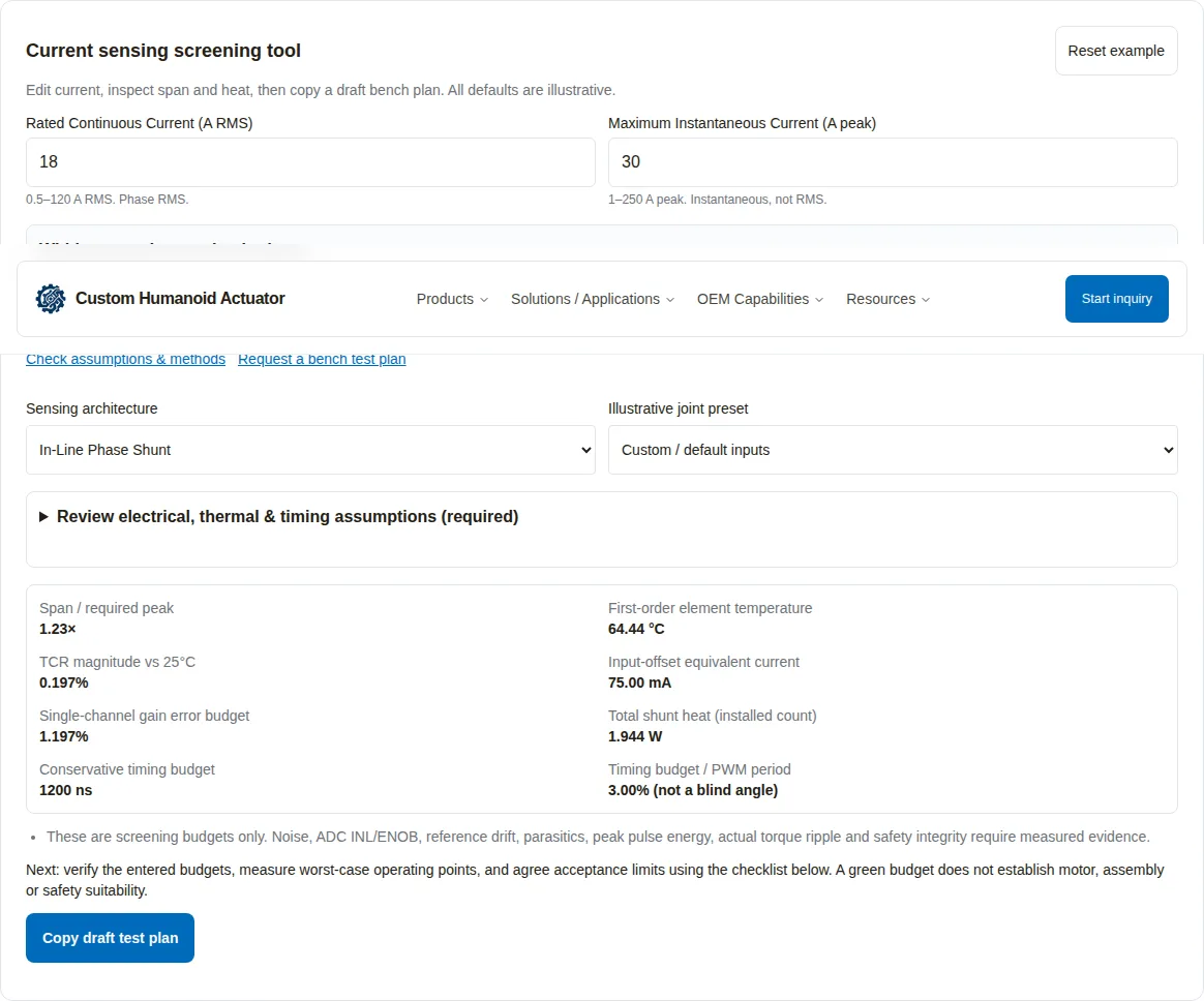
Current sensing screening tool
Edit current, inspect span and heat, then copy a draft bench plan. All defaults are illustrative.
Within entered screening budgets
Review electrical, thermal & timing assumptions (required)
Every field is required. Replace example values with datasheet limits and measurements. Temperature uses a 25°C resistance reference. Low-side heat uses conduction factor 1 as an upper bound.
- Span / required peak
- 1.23×
- First-order element temperature
- 64.44 °C
- TCR magnitude vs 25°C
- 0.197%
- Input-offset equivalent current
- 75.00 mA
- Single-channel gain error budget
- 1.197%
- Total shunt heat (installed count)
- 1.944 W
- Conservative timing budget
- 1200 ns
- Timing budget / PWM period
- 3.00% (not a blind angle)
- These are screening budgets only. Noise, ADC INL/ENOB, reference drift, parasitics, peak pulse energy, actual torque ripple and safety integrity require measured evidence.
Next: verify the entered budgets, measure worst-case operating points, and agree acceptance limits using the checklist below. A green budget does not establish motor, assembly or safety suitability.
Four decisions before releasing a current-sensing design
| Decision | Basis | Next action |
|---|---|---|
| Reserve actual output swing | ADC rails alone overstate usable span; amplifier output swing and reference bias matter [1]. | Inspect the selected part and scope the largest phase-current transient. |
| Track temperature from the resistance reference | Ambient temperature and self-heating both change shunt resistance [4]. | Measure the element and terminal temperatures on the assembled PCB. |
| Prove sample validity across operating points | In-line recovery and low-side vector duration both affect valid sampling [2,3]. | Capture ADC timing and amplifier output at the worst modulation. |
| Keep screening separate from safety validation | A budget result does not establish an application performance level [7]. | Agree acceptance limits and validate the complete control system. |
Supporting references: [1] output limits, [4] temperature effects, [2] PWM recovery, [3] low-side design, [7] safety scope.
Choose topology using testable trade-offs
In-line sensing measures the phase conductor; low-side sensing needs a suitable inverter switch state. Neither architecture is automatically qualified for a humanoid joint. The intended control envelope and measured feedback quality determine suitability. PWM recovery and low-side reference designs provide distinct engineering constraints.
| Architecture | Strength / cost driver | Boundary | Test evidence |
|---|---|---|---|
| In-line shunt | Direct phase measurement; amplifier common-mode capability adds cost | Switching recovery, output swing, shunt heat | Scope settling across bus voltage, temperature and modulation |
| Low-side three-shunt | Ground-referenced sensing; extra channel and selection logic | Valid sample channels depend on switching sequence | Verify shortest window and channel selection in every sector |
| Low-side two-shunt | One fewer resistor and sensing channel | Reconstructed third phase is not independent evidence | Check simultaneous channel validity and reconstruction error |
| Magnetic / isolated IC | Can reduce insertion resistance; isolation and packaging add constraints | Conductor loss, noise, external fields and isolation are part-specific | Request sensitivity, primary resistance, noise spectra and exact isolation rating |
No current-price survey or supplier quotation is available here. Compare the complete BOM, layout area, calibration effort, thermal integration and firmware validation rather than a claimed universal dollar saving. Magnetic device selection needs the exact ordering code. Manufacturer catalog
Calculation methods, assumptions and known unknowns
The tool is deterministic and runs locally. It assumes a mid-reference bidirectional output, a 25°C nominal shunt, symmetric rail reserve and positive worst-case error magnitudes. Defaults are scenarios, not component recommendations. Equations below define this screening model; they do not replace datasheet limits.
| Output | Equation / convention | Limitation |
|---|---|---|
| Nominal shunt heat | P = I_RMS² × R25; N = 2 for two-shunt, otherwise 3 | Low-side conduction factor is conservatively 1; actual waveform and phase heating may differ |
| First-order element temperature | T = T_local + P × Rθ | Ignores resistance feedback, mutual heating and transient thermal impedance |
| TCR magnitude | eT (%) = |T − 25°C| × TCR / 10,000 | Magnitude budget; not signed compensation or post-calibration residual |
| Bounded current span | Rmax = R25(1 + (tolerance + eT)/100); Gmax = G(1 + gain_error/100); Imax = max(0, ((Vref/2 − rail_reserve)/Gmax − |Vos|)/Rmax) | First-order hot resistance estimate; reserve must cover real output swing and reference/transient errors |
| Nominal code width | ΔI = Vref / (2^bits × G × R25) | Code width is not noise, effective resolution or total accuracy |
| Input offset equivalent | I_offset = |Vos| / R25 | Single-channel input-referred error; no mechanical torque amplitude implied |
| Single-channel gain budget | tolerance + amplifier gain error + eT | Arithmetic magnitude budget; phase mismatch and correlated errors need channel data |
| Conservative timing sum | t_required = dead_time + settling/filter_delay + ADC_acquisition | Compare with the entered transition-to-next-edge interval, including recovery; overlap and trigger placement depend on hardware |
The 15% span-reserve warning, 95°C temperature budget and 1 W per-shunt budget are illustrative project choices. Replace them with approved design limits. Missing noise, ADC errors, pulse duration, motor saliency, mechanical compliance and safety analysis stay unknown; the tool reports no torque-ripple amplitude or blind-sector angle.
Physical thermal and sense-tap considerations are described by ROHM and TI. The thermal estimate uses nominal cold resistance, so it can understate hot dissipation; confirm the full thermal model before accepting a near-limit result.
Thermal drift and Kelvin routing must be tested together
A 20 A RMS current through a 2 mΩ shunt gives 0.8 W nominal per phase. With 25°C/W element-to-local-ambient resistance and 30°C ambient, the first-order element estimate is 50°C. A 50 ppm/°C TCR then gives a 0.125% magnitude relative to 25°C. These are derived example values, not measured product ratings.
Sense at the manufacturer-specified element taps. Copper and solder included in a two-wire pickup can introduce additional temperature-dependent resistance. Validate the actual PCB because a nominal resistor specification does not characterize the complete path. PCB/TCR evidence · shunt layout guidance
Measure a valid sampling interval, not a guessed blind angle
At 25 kHz the PWM period is 40,000 ns. An example 300 ns dead time, 650 ns recovery and 250 ns acquisition gives a conservative 1,200 ns budget, or 3% of a period. Against an entered 2,000 ns available interval, the margin is 800 ns. This ratio alone says nothing about electrical blind angle or maximum modulation.
| Operating point | Capture | Decision |
|---|---|---|
| High modulation / field weakening | Phase channel selection, PWM state, amplifier output, ADC aperture | Are at least the required channels simultaneously valid? |
| High bus voltage / fast edges | Switching node and sense output with suitable probes | Does common-mode recovery settle inside the actual window? |
| Hot and cold electronics | Same acquisition settings, source impedance and filter | Does the worst-case residual stay within the agreed error budget? |
| Changed firmware or PWM mode | Trigger phase, blanking and reconstruction logs | Repeat the validation; timing does not transfer automatically |
In-line measurement also needs recovery after PWM transitions. TI explains this limitation. Low-side sample availability depends on vector duration and the implementation. TI reference design
Bench protocol: zero, gain, temperature and switching recovery
| Step | Method | Record / acceptance basis |
|---|---|---|
| 1. Establish real zero | Ensure no motor or regenerative current; allow settling | Per-channel mean, noise spread, temperature and uncertainty; agreed offset budget |
| 2. Apply electrical references | Inject positive and negative current points with a calibrated current reference | Raw ADC codes, slope/intercept, reference uncertainty and independent residual points |
| 3. Repeat at temperature | Evaluate cold start, thermal soak and rated duty | Shunt/terminal temperatures, gain drift and device derating against project limits |
| 4. Validate dynamic sampling | Capture switching edges, amplifier output and acquisition interval | Settling residual in each switching sector and worst operating point |
| 5. Check overload separately | Use a controlled pulse plan within qualified hardware limits | Pulse width, repetition, protection path and resistor pulse-energy limits |
| 6. Verify final assembly | Read back coefficients; repeat an independent check | Serial, PCB/firmware versions, calibrated instruments, limits and deviations |
Electrical current calibration and current-to-torque verification answer different questions. Use the electrical reference to calibrate sensing; use a calibrated shaft-torque sensor and controlled load to study mechanical response. A torque measurement alone cannot isolate current-channel gain error.
Prepare a traceable bench-test RFQTorque spectra: identify contributions before assigning a cause
A stationary phase-current offset becomes a rotating disturbance after the Park transform; unequal channel gains can introduce a second-harmonic component. Their actual torque amplitudes also depend on channel signs, transformation conventions, current control dynamics, motor properties and gearing. This page therefore avoids converting a single offset or tolerance number into a certified ripple figure.
| Quantity | Known from this tool | Evidence still required |
|---|---|---|
| Nominal ADC code width | Computed from Vref, bits, gain and shunt | Noise spectrum, ENOB, INL, reference drift and sample settling |
| Input-offset equivalent current | Vos divided by nominal resistance | Per-channel residuals across temperature and startup conditions |
| Phase mismatch | Not calculated | Matched channel measurements, covariance and calibration residuals |
| Shaft torque ripple | Not calculated | Synchronized torque/current/angle logs, sensor bandwidth and uncertainty |
| Force / collision sensitivity | Not calculated | Transmission friction, compliance, contact geometry and validated system response |
Use electrical frequency from measured rotor angle and pole pairs when comparing spectra. Distinguish sensing errors from cogging, inverter dead time, gearing and load vibration; an isolated spectral peak is insufficient evidence of a sensing fault.
Worked decision examples: assumptions, result and next action
All five cases below are derived illustrations. None is a customer test record or a released actuator specification. Presets in the tool are separate editable examples and may intentionally reveal a budget conflict.
| Scenario / assumptions | Derived result | Decision / next measurement |
|---|---|---|
| Case 1: Wrist, 8 A RMS, 5 mΩ shunt | Nominal power = 8² × 0.005 = 0.320 W per in-line element | Check noise and conductor loss; small code width alone does not establish gentle-touch sensitivity |
| Case 2: Elbow, two low-side shunts, 16 A RMS, 2.5 mΩ | Duty-factor-1 heat bound = 0.640 W each, 1.280 W for two | Measure actual conduction and channel validity; no unconditional suitability rejection |
| Case 3: Knee, 75 A instantaneous peak, 1 mΩ, gain 20, 3.3 V reference | Ideal rail span = ±82.5 A; 0.15 V reserve reduces nominal span to ±75 A before error allowances | Reserve is already consumed; revisit gain/resistance and verify pulse overload |
| Case 4: Hip holding, 35 A phase RMS, 0.75 mΩ, 55°C local ambient, 18°C/W | P = 0.91875 W; first-order T = 71.5375°C; at 20 ppm/°C, drift magnitude = 0.0931% vs 25°C | For a stationary rotor, measure actual per-phase RMS; do not assume equal three-phase heating |
| Case 5: Finger, 15 mΩ, gain 20, 3.3 V, 16-bit ADC | Nominal code width = 3.3 / (65536 × 20 × 0.015) = 0.1678 mA/LSB | Compare with measured noise and calibration residual; no sub-gram force claim follows |
Misuse, cost and safety limits
For an ideal three-wire motor, ia + ib + ic = 0. An independently measured residual may support diagnostics, but reconstructing ic = −ia − ib makes that sum zero by construction. It cannot independently detect a failed channel.
DC bridge current is a different quantity. With ideal upper-switch states sa, sb, sc, iDC = sa·ia + sb·ib + sc·ic. A source-side measurement may also include DC-link capacitor and auxiliary currents. Compare synchronized switching-state models and independent measurements rather than equating bus current with the phase sum.
ISO 13849-1 defines a control-system design methodology; its public scope explicitly leaves application safety functions and required performance levels to application-specific determination. No diagnostic coverage percentage, stop time, PL, SIL or certification is established by this page. Official ISO scope
| Risk | Consequence | Mitigation / alternative |
|---|---|---|
| Using within-budget as product acceptance | Unmodeled thermal feedback, noise or overload can dominate | Require measured component/assembly limits and a signed acceptance protocol |
| Reducing shunt resistance only to cut heat | Signal-to-noise and offset-equivalent current worsen | Compare total error at the required bandwidth; consider an appropriate magnetic sensor |
| Selecting a cheaper topology without validation cost | Firmware and calibration effort may exceed BOM savings | Quote channels, test time, fixture costs, thermal integration and lifetime validation separately |
| Reusing one sampling plan across operating modes | High modulation, regeneration or changed filtering invalidates measurements | Revalidate operating extremes and firmware revisions; limit the envelope until proven |
| Assuming sensing alone ensures safe torque limiting | Common-cause and mechanical hazards remain unaddressed | Complete the application hazard assessment and independent safety validation |
Frequently asked questions
Tool scope
Is a within-budget result a hardware pass?
No. It compares entered values with illustrative budgets. It cannot establish component derating, noise performance, control stability, pulse survival or safety integrity.
Which current convention does the tool use?
Rated current is phase RMS over the evaluated waveform. Maximum instantaneous current is the largest absolute phase current including transients. A sinusoidal amplitude is RMS × √2; do not apply that conversion to a DC holding phase.
Why does the isolated sensor mode show no calculated result?
A magnetic sensor uses sensitivity in V/A, offset, conductor loss and delay from its own datasheet. Applying a shunt resistance and amplifier gain would give an unrelated result. Use the manual RFQ checklist instead.
Does a 16-bit ADC guarantee better torque precision?
No. Nominal code width excludes noise, reference error, INL, effective resolution and motor mechanics. Measure the complete acquisition chain at the intended bandwidth.
Topology
Is in-line current sensing mandatory for humanoid joints?
No universal topology requirement is established here. In-line measurement avoids low-side switch-conduction restrictions but still needs PWM transient recovery. Select topology using measured sampling availability, losses, cost and the required control performance.
When can two low-side shunts be used?
For a three-wire motor, the third current can be reconstructed from two synchronized valid measurements. Validate which channels are observable at every switching sector and operating point. Reconstruction is not independent third-channel redundancy.
Are magnetic current sensors lossless?
No. Devices with an integrated primary conductor have insertion resistance and I²R heat, and the electronics draw supply power. External-field and isolation limits also depend on the selected component.
Thermal
Why is thermal drift referenced to 25°C?
The tool assumes shunt nominal resistance and tolerance are specified at 25°C. It uses the estimated element temperature relative to that reference, including local ambient and self-heating. Use the actual calibration reference for a calibrated model.
Is 95°C a universal shunt temperature limit?
No. It is the default example project budget. The allowed temperature depends on the resistor, terminals, PCB, solder assembly, derating curve and qualified service profile.
Does the heat result cover short current peaks?
No. The first-order estimate uses rated RMS and nominal resistance. Pulse duration, repetition, transient thermal impedance and pulse-energy derating must be assessed separately.
Timing
Can a blind-sector angle be calculated from PWM frequency alone?
No. Switching sequence, modulation, current waveform, channel selection, blanking and ADC timing are needed. The tool compares an entered interval including switching recovery with a conservative timing sum; it does not calculate blind-sector angles.
How should the available sampling interval be measured?
At the worst modulation, speed and bus voltage, measure from the commanded switching transition to the next disruptive edge for the selected channels. This available interval includes dead time and analog recovery. Compare it with the complete timing sum; do not enter only the already-settled portion.
Calibration
Is a dynamometer a current calibration reference?
Use a calibrated electrical current reference for current-channel gain and offset. A dynamometer with a traceable torque sensor independently checks current-to-torque behavior, friction and harmonics.
How should startup zero calibration be tested?
First establish that actual current is zero; disabled gates alone may not ensure this during motion or regeneration. Record mean offset, spread, temperature and settling. Reject unexplained drift before enabling the drive.
Can electrical-frequency peaks identify sensing faults by themselves?
No. Offset and channel imbalance can contribute fundamental and second-harmonic components, but torque spectra also include cogging, mechanics, inverter nonlinearity and controller dynamics. Correlate synchronized electrical and mechanical records.
Safety and RFQ
Does a current-sum check establish PL d?
No. A safety function needs application-specific requirements, architecture analysis, reliability evidence, diagnostic validation and common-cause assessment. ISO 13849-1 does not prescribe the required performance level for every application.
Is DC-bus current the sum of phase currents?
No. For an ideal three-wire motor, ia + ib + ic = 0. With upper-switch states sa, sb and sc, ideal instantaneous bridge DC current is sa·ia + sb·ib + sc·ic. DC-link capacitor current and measurement position must also be considered.
What should accompany a supplier acceptance report?
Provide serial number, PCB and firmware revisions, instrument calibration and uncertainty, current convention, raw zero/gain data, thermal operating point, sampling scope captures, agreed limits and deviations. A calculator export is only a draft test request.
Primary sources and evidence boundaries
Links checked 2026-11-03. Product availability, pricing and certification are not inferred from these sources. Manufacturer examples explain design constraints; numeric examples elsewhere are calculations under stated assumptions. The ISO citation uses its public scope, not a claim of access to the full paid standard.
Next scheduled review: . Recheck earlier when the selected sensor, PCB layout, firmware, PWM mode, calibration procedure or source revision changes.
- TI INA241x datasheet, Rev. D
Part-specific gain, output swing, common-mode limits and PWM recovery. These values are not universal acceptance criteria.
- TI SBOA160D: Low-Drift, Precision, In-Line Motor Current Measurements With PWM Rejection
Why in-line signals still suffer common-mode switching disturbances and settling delay.
- TI TIDA-00778 current-sensing reference design
Examples of one-, two- and three-shunt sensing and active-vector timing. Reference-design results do not qualify this actuator.
- ROHM: Effect of PCB Design on Temperature Coefficient of Resistance
Ambient, self-heating and copper sense-tap placement affect resistance error.
- TI SBAA460: Shunt Resistor Selection for Isolated Data Converters
Shunt selection, Kelvin layout, thermal effects and calibration considerations.
- Allegro integrated current sensor product catalog
Sensor-specific sensitivity, bandwidth, primary resistance and isolation variants. Request the exact ordering-code datasheet.
- ISO 13849-1:2023 official scope and abstract
Safety-related control design methodology; the public abstract does not prescribe application PLr or sensor trip limits.
Turn the screening into an agreed current-sensing test plan
Send the joint operating waveform, phase-current convention, bus voltage, sensing topology, exact components, thermal envelope, PWM/ADC configuration and required uncertainty. Attach the copied draft plus drawings and available scope captures. Acceptance values, test capability, cost and lead time require project review.
| Package | Include | If unavailable |
|---|---|---|
| Electrical and thermal | RMS/instantaneous peak, pulse profile, component codes, PCB layout and temperature limits | Mark unknown; request a characterization plan before quoting acceptance |
| Acquisition | Switching sequence, trigger, filters, ADC settings, firmware revision and raw captures | Restrict the evaluated operating envelope and measure the missing windows |
| Acceptance and traceability | Agreed limits, current/torque references, instrument uncertainty, serial and revision fields | Start with a draft protocol; no performance or certification claim |
Inquiry Email
Include target torque/speed, quantity, and delivery location.
Application Engineer
WhatsApp Engineering Support
Talk directly about drawings, torque-speed targets, and RFQ data gaps.
Related engineering checks: continuous torque testing · compliance testing · contact engineering.