Crossed Roller Bearings in Custom Humanoid Actuators: Moment Rigidity, Preload Sizing, Dynamic Shock Tolerance, and Sourcing Acceptance Protocols
Compare crossed roller bearings for humanoid actuators: moment rigidity, thermal fits, shock loads, and supplier acceptance checks. Prepare your bearing RFQ.
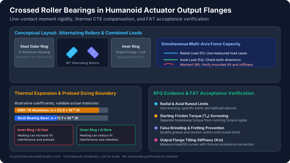
Crossed roller bearings (CRBs) can support combined radial, axial, and overturning loads in a compact humanoid actuator output stage. Select them by mounted moment stiffness, temperature-dependent fit, friction torque, and the actual load spectrum. An angular contact bearing pair remains a candidate when its support span, speed capability, serviceability, and measured stiffness fit the joint envelope. A catalog load rating alone cannot decide between them.
Published and reviewed: 4 November 2026. This global engineering and procurement guide is for teams sourcing custom rotary humanoid actuators. It covers output bearings, housing interfaces, preliminary load screening, and supplier acceptance evidence. Numerical examples are hypothetical calculations, not measured robot results or product ratings. Final limits depend on the selected bearing series, mounting geometry, lubricant, seals, temperatures, and duty cycle; this article does not establish a certified joint rating.
Executive Sourcing & Engineering Summary
- Moment rigidity: Set an allowable flange tilt from the robot's deflection budget, then request a mounted moment-versus-angle curve. Contact geometry alone does not establish a universal stiffness advantage.
- Preload and thermal fit: Specify the manufacturer's clearance designation and measured condition. A warming aluminum housing bore can loosen around a steel outer ring, while a warming aluminum hub can increase interference against an inner ring.
- Dynamic shock tolerance: Separate dynamic equivalent load, peak static load, housing strength, and fastener checks. Choose factors from the applicable catalog and recorded load cases.
- Small-angle oscillation: Treat grease replenishment and fretting as application tests. Control-loop frequency is not necessarily the frequency of physical bearing motion.
- Sourcing acceptance: Agree on inspection methods, numerical limits, sampling, and evidence before the pilot order. Neither a precision grade nor a supplier certificate substitutes for mounted verification.
For an integration review, send your joint CAD envelope, simultaneous loads, duty cycle, and pilot quantity to our engineering inquiry desk. The custom humanoid actuator modules overview explains the available module scope.
1. The Output Stage Dilemma: Why Gearbox Ratings Alone Do Not Prevent Joint Wobble
Reducer torque capacity describes only part of the load path. External forces can pass through the output flange, bearing rings, housing shoulders, bolts, and limb structure. Some reducers contain an output support bearing; others require a separate support arrangement. Draw that load path before assigning the bearing all external bending loads or assuming the reducer isolates them.
A useful first approximation relates overturning moment to angular deflection:
External force F at offset L:       M = F × L
Mounted moment stiffness:          Km = M / theta
Limb-tip displacement at radius R: delta ≈ R × theta
Use radians for theta in the small-angle displacement calculation.
For a hypothetical 0.5 m link with a 0.1 mm bearing-related displacement budget, allowable bearing tilt is 0.0002 rad, or 0.2 mrad. At an assumed 160 N·m operating moment, the required secant stiffness is 800 N·m/mrad. This is an allocation to the mounted bearing assembly, not a rating inferred from bore diameter. Housing, fastener, reducer, and link compliance require their own allocations.
Record the moment range and loading direction for every stiffness claim. Preloaded contacts can be nonlinear, so stiffness near zero load may differ from stiffness at the maximum working moment. Ask the supplier whether its curve includes the mounting flange and fixture compliance. Subtracting fixture motion matters when two candidates appear close.
Walking, stumbling, landing, and emergency-stop loads should come from a defined simulation or measurement program. Robot mass and walking speed alone do not establish a universal impact acceleration, bearing force, or service-life reduction. Preserve simultaneous force components and their lever arms instead of combining unrelated maximum values without explanation.
2. Bearing Architecture Mechanics: Crossed Roller Bearings vs. Angular Contact Pairs
2.1 Crossed Roller Bearings
Alternating roller orientations allow a crossed roller ring to support combined loading in one compact assembly. This can simplify the output support when axial space is scarce. The complete bearing and mounting design still determines stiffness: roller dimensions, raceway geometry, preload, ring section, housing support, and bolt arrangement all matter.
Preload can reduce clearance and increase initial stiffness, but it also changes friction, contact loading, and temperature sensitivity. A preloaded ring remains elastically compliant. Do not translate “zero clearance” into zero angular deflection or zero actuator backlash.
2.2 Duplex Angular Contact Ball Bearings
A back-to-back angular contact pair can provide useful overturning stiffness through its effective support span. Its performance depends on contact angle, bearing size, preload, spacing, and shaft and housing compliance. Compare the entire pair and its mounting stack against the crossed roller assembly, including mass and available axial length.
Angular contact bearings may be attractive where speed and friction are priorities. They still require lubrication, alignment, and thermal checks; neither pure rolling nor a fixed friction advantage should be assumed for every operating condition.
2.3 Four-Point Contact Ball Bearings
A four-point contact design can provide a compact alternative for suitable combined loads. Contact conditions and friction depend on the balance of axial, radial, and moment loading. Ask for application-specific limits rather than assuming all such designs have the same reversal behavior.
Use this decision matrix to structure comparable supplier responses:
| Selection question | Crossed roller ring | Integrated-raceway design | Angular contact pair | Evidence to request |
|---|---|---|---|---|
| Combined load support | Compact single assembly | Depends on the complete custom design | Depends on arrangement and support span | Simultaneous load cases and rating method |
| Mounted moment rigidity | Sensitive to preload and ring support | Includes structural part compliance | Sensitive to spacing and preload | Moment-angle curve with fixture definition |
| Axial packaging | Often useful where length is constrained | May remove interfaces and separate rings | Includes two bearings and retention stack | Complete section drawing and mass breakdown |
| Peak shock | Check contact loads and mounting strength | Also check structural raceway material | Check both bearing reactions | Static equivalent load and structural assessment |
| Friction and reversal | Measure with specified grease and seals | Measure on representative assemblies | Measure with production preload | Breakaway and running torque traces |
| Thermal fit | Check both ring interfaces | Include structural thermal gradients | Check radial fits and axial preload path | Cold/hot fit analysis and mounted tests |
| Sourcing cost | Catalog availability may simplify sampling | Tooling, metrology, and scrap affect cost | Matched pairs and spacers affect assembly | Prototype and production quotes at stated quantities |
| Repair and replacement | Ring may be replaceable | Structural part may require replacement | Pair and spacers need controlled replacement | Service procedure and replacement acceptance checks |
3. Structural Integration: Standalone Cartridges vs. Direct Raceway Machining
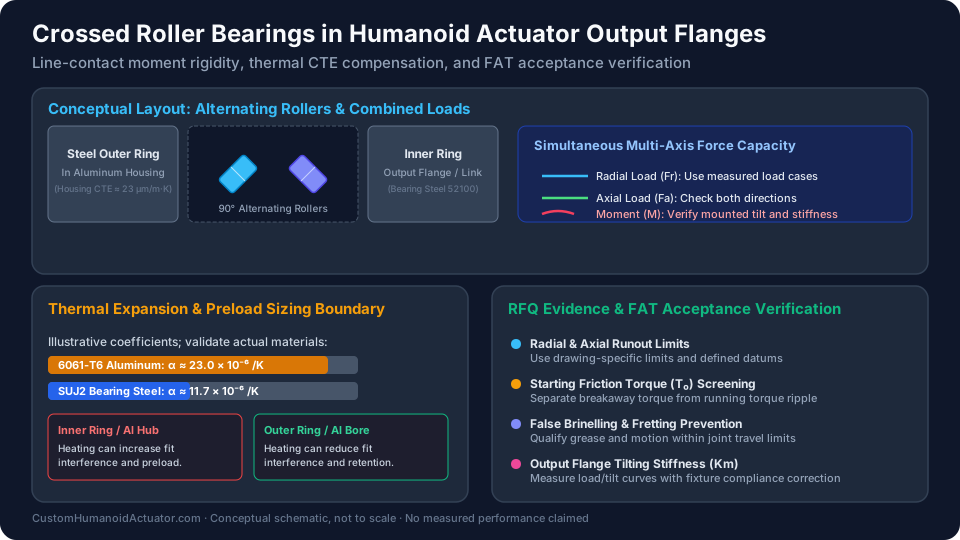
Conceptual schematic; not to scale. It illustrates load paths and review questions, not tested bearing performance.
A standalone ring separates the bearing from the actuator housing. That makes early sampling, replacement, and comparison easier, although flange and clamp interfaces add tolerance and compliance. Some designs have mounting holes in both rings; others rely on precision shoulders and retaining plates. Follow the selected model's mounting instructions.
An integrated raceway can reduce interfaces, but the benefit must be calculated from the actual CAD assembly. There is no universal mass saving, axial reduction, or stiffness improvement. It also changes scrap exposure: a damaged raceway may require replacing a costly housing or reducer flange.
Ordinary aluminum housing material is not a substitute for a qualified rolling-contact raceway. An engineered steel insert or suitable hardened steel structural part requires controlled material condition, hardness depth, finish, geometry, and distortion after heat treatment. Titanium or a surface coating should not be accepted as a drop-in raceway solution based on material name alone.
For early production, compare the replaceable-ring baseline with an integrated proposal using the same drawing revision and inspection requirements. Include tooling cost, sample yield, replacement access, metrology time, and delivery risk. The custom actuator housings and interfaces page provides a route for discussing bearing seats and flange datums.
4. The Thermal Expansion Trap: Aluminum Housings vs. Steel Bearing Rings
4.1 Fit Change Is Not the Same as Internal Clearance Change
Consider an illustrative 100 mm interface heated uniformly from 20°C to 80°C. Using assumed expansion coefficients of 23.0 × 10⁻⁶/K for aluminum and 11.7 × 10⁻⁶/K for steel:
Differential diametral growth
= D × deltaT × (alpha_aluminum - alpha_steel)
= 100 mm × 60 K × 11.3 × 10^-6/K
= 0.0678 mm = 67.8 micrometers
This is a diametral free-expansion difference, not a predicted 67.8 micrometer change in roller clearance. Actual ring deformation depends on interference, ring and housing thickness, support, clamping, and different component temperatures.
For a steel outer ring in an aluminum bore, uniform heating tends to reduce interference because the bore grows faster. Cooling tends to tighten that interface. For a steel inner ring over an aluminum hub, heating tends to increase interference; cooling tends to loosen it. Inner-ring expansion can increase internal preload, while loss of outer-ring retention can cause movement or fretting. Neither interface alone predicts the complete assembly's final clearance.
Motor heating also creates gradients: the hub, outer housing, rings, and rollers may not reach the same temperature. Use the actual material data and measured temperatures for design release. A free-expansion calculation is a screening step that identifies where a coupled fit analysis is needed.
4.2 Sourcing Solutions: Fit Tolerances and Preload Selection
Clearance codes are manufacturer- and series-specific. Do not assume that V0, CC0, or a similarly named class has the same numerical meaning across suppliers. Request the dimensional clearance or preload definition, reference temperature, measurement load, and installed condition. A housing-bore tolerance such as H7 alone does not define the resulting bearing fit.
| Interface or specification | Potential concern | RFQ requirement | Verification |
|---|---|---|---|
| Steel outer ring in aluminum bore | Cold tightening or hot retention loss | Bore limits, ring OD limits, wall section, and retention scheme | Worst-case fit stack and cold/hot mounted checks |
| Steel inner ring on aluminum hub | Hot interference growth | Hub limits, ring ID limits, material, and temperature map | Contact/fit analysis and measured torque |
| Bolted ring or clamp flange | Ring distortion from uneven support | Flatness, tightening sequence, torque, and shoulder definition | Runout and friction before and after final fastening |
| Factory-set preload | Installed preload differs from free-ring condition | Supplier code and numerical definition at reference temperature | Agreed clearance or preload measurement method |
| Steel insert or sleeve | Added interface and uncertain restraint | Insert geometry, retention, contact pressure, and thermal model | Representative assembly tests across duty cycle |
| Alternative roller or ring material | Changed contact and thermal behavior | Qualified material pair, load limits, and lubrication compatibility | Supplier design review and dedicated qualification |
A sleeve, clearance class, ceramic roller, or selected fit does not by itself guarantee freedom from binding. Validate the assembled actuator at its specified cold and hot limits, including startup after soak and repeated thermal cycles. Temperatures such as -20°C and +85°C are possible project test points only when the selected bearing, seals, and grease are approved for them.
5. Tribology & Failure Modes: Mitigating False Brinelling in Micro-Dithering Joints
Small oscillations can repeatedly load the same raceway region without replenishing lubricant effectively. Fretting and false brinelling can then produce raceway wear marks and torque disturbance. These wear processes must be distinguished from true brinelling caused by plastic indentation under overload.
The THK nominal-life and selection guidance specifically flags small oscillation angles as an application needing attention to oil-film formation and fretting. It also directs users to seek manufacturer input when including preload in life calculations. These boundaries matter when a humanoid joint spends much of its duty cycle holding posture.
A controller updating at 1 kHz does not prove that the bearing oscillates at 1 kHz. Measure the actual output angle, amplitude, frequency distribution, load, temperature, and dwell time. Use that record to define the test. Do not assume a universal number of operating hours before damage appears.
Specify a supplier-approved lubricant, fill quantity, seal compatibility, and replenishment method. Base oil or thickener names alone do not establish fretting resistance, and a generic additive recommendation should not override the bearing manufacturer's compatibility requirements. Coatings also require qualification for adhesion, rolling fatigue, dimensional effects, and lubricant interaction.
A periodic larger-angle motion may redistribute lubricant, but its amplitude and timing must fit the mechanism's travel limits, cables, collision envelope, and operating state. Do not command an unrestricted 360° sweep in a limited-travel joint. Confirm whether the proposed motion improves the representative oscillation test before adding it to the maintenance procedure.
For transit, define restraints and vibration isolation around the actual shipping configuration. A motor brake alone may not prevent micro-motion at every loaded interface. Compare torque traces before and after a representative shipment or vibration test, and inspect qualification samples where appropriate.
6. Sizing and Calculation Framework: Moment Load and Equivalent Ratings
6.1 Dynamic Equivalent Radial Load Formulation
For the crossed roller ring method described in the THK selection reference above, the calculation combines radial force, axial force, and a moment-related term:
P = X × (Fr + 2M/dp) + Y × FaUse consistent units: newtons and N·m with pitch diameter in meters, or newtons and N·mm with pitch diameter in millimeters. Pitch diameter is the roller-center circle; it is not the bearing bore or mounting-bolt circle. The manufacturer's load-factor selection depends on the ratio Fa / (Fr + 2M/dp). Verify the applicable series and catalog revision before applying this method to a supplier proposal.
6.2 Worked Engineering Calculation: Humanoid Knee Output Bearing
The following inputs are a hypothetical screening case, retained so buyers can reproduce the arithmetic. They are not measured walking loads, a selected bearing, or an approved knee design:
dp = 0.080 m roller pitch diameter
Fr = 1,800 N
Fa = 950 N
M  = 160 N·m
Assumed application load factor fw = 1.5
First, the moment-related term is 2 × 160 / 0.080 = 4,000 N. The combined radial term is therefore 1,800 + 4,000 = 5,800 N. The ratio 950 / 5,800 is approximately 0.164, so this example uses the catalog branch X = 1 and Y = 0.45:
P = 1 × 5,800 + 0.45 × 950
  = 6,227.5 N

fw × P = 1.5 × 6,227.5
       = 9,341.25 N ≈ 9.34 kN
The assumed factor is a screening input, not a universal heel-strike multiplier. If a measured load already captures an impact, agree how to account for remaining uncertainty without silently applying the same allowance twice. Dynamic rating selection still needs the operating spectrum, motion, life target, reliability basis, and preload treatment.
6.3 Static Shock and Moment Stiffness Are Separate Checks
Do not use the dynamic equivalent load above as the static equivalent load. Obtain the selected manufacturer's static combined-load method and calculate the maximum static equivalent load P0 from the actual simultaneous peak case. Then compare C0/P0 with the application-specific static safety factor agreed with the supplier.
For example, only if a separate static calculation establishes P0 = 8 kN, an agreed factor of 3 would require C0 ≥ 24 kN. Both numbers are hypothetical. This conditional arithmetic is not an ISO-mandated humanoid limit and does not establish survival of a drop, fastener slip, flange yielding, or raceway edge loading.
Also verify the mounted moment-angle curve against the deflection allocation from Section 1. Passing contact-load screening does not establish adequate positioning rigidity. For a custom load path, discuss the analysis and inspection scope through precision machining and metrology.
7. The 10-Point RFQ Specification Checklist for Custom Actuator Bearings
Include these requirements in the drawing and quotation package so suppliers price the same assembly and acceptance scope:
- Envelope and interfaces: Inner and outer diameters, width, roller pitch diameter, bolt pattern, shoulders, and cable clearance; identify which ring rotates.
- Simultaneous loads: Radial, axial, and moment histories with coordinate definitions, lever arms, peak duration, reversals, and uncertainty allowances.
- Rigidity budget: Allowable mounted tilt and moment-angle measurement range, including loading and unloading hysteresis and fixture correction.
- Preload definition: Manufacturer series and class, numerical definition, reference temperature, and free-ring versus installed measurement condition.
- Thermal fit: Housing and hub materials, dimensional tolerances, component temperature map, retention scheme, and cold-start requirements.
- Precision and datums: Runout characteristic, measuring surface, diameter range, measurement load, mounting condition, and applicable catalog tolerance table. A P4 or P5 label alone does not define a universal micrometer limit.
- Friction acceptance: Breakaway torque after a defined dwell, running torque at stated speed, direction, temperature, seals, and load. Define ripple as peak-to-peak or another explicit metric.
- Lubrication and motion: Approved grease and fill quantity, storage, oscillation spectrum, maintenance interval, and any qualified replenishment routine.
- Environmental protection: Dust, water, corrosion, and cleanliness requirements for the assembled joint. A bearing seal designation alone does not establish the actuator's IP rating.
- Traceability and release: Drawing revision, material and heat-treatment records, inspection sampling, serial or lot identification, report format, nonconformance handling, and substitution approval.
Use the custom humanoid actuator ODM RFQ guide to assemble the wider motor, reducer, electronics, and pilot-build package. Resolve missing inputs before treating two quotes as comparable.
8. Factory Acceptance Testing & Quality Verification Protocols
The six protocols below are a buyer-side acceptance template. They are proposed methods, not completed tests or universal industry limits. Populate numerical thresholds from the drawing, selected catalog, and joint requirements before placing the order. Agree which tests cover every pilot unit and which consume qualification samples.
| Verification protocol | Test setup and conditions | Acceptance basis | Required evidence |
|---|---|---|---|
| Radial and axial runout | Measure defined surfaces relative to specified datums, with final clamping and bolt sequence | Drawing limits for the selected size and series; distinguish bearing-ring from output-flange runout | Serialized results, fixture description, gauge capability, and calibration record |
| Breakaway and running torque | Control grease, dwell, temperature, load, speed, direction, and measurement range | Separate starting maximum, running band, and explicitly defined ripple limit | Torque-angle traces in both directions and instrument uncertainty |
| Overturning moment rigidity | Apply calibrated moments in both directions and measure flange tilt; characterize fixture compliance | Project minimum stiffness and maximum hysteresis over the stated load range | Load/unload curves, fixture correction, and assembly revision |
| Thermal fit and retention | Soak the mounted assembly at approved cold/hot endpoints until temperatures stabilize; check startup and retention | No binding, unacceptable retention loss, or torque/runout beyond agreed limits | Ring, hub, and housing temperatures; torque logs; post-cycle inspection |
| Oscillation and fretting endurance | Reproduce measured angle, frequency, load, dwell, lubricant, and temperature on qualification samples | Agreed torque drift and inspected raceway condition against baseline | Motion/load record, cycle count, before/after traces, and teardown images |
| Shock and transit screening | Apply an agreed pulse, direction, mounting boundary, or shipping vibration profile on designated samples | No unacceptable permanent tilt, torque/runout change, cracking, or retention loss | Calibrated input trace, fixture details, sample identity, and post-test measurements |
Report measurement uncertainty alongside the limit. A nominally passing value is not persuasive if gauge uncertainty is comparable to the allowed variation. Keep raw traces and failure dispositions, not just a green summary sheet. If the supplier changes grease, ring source, heat treatment, or a structural interface, define which qualification evidence must be repeated.
The humanoid actuator evaluation protocols procurement guide helps place bearing checks within the complete actuator validation sequence. Agree on the bearing evidence package during feasibility review so fixture cost and sample consumption are included in the quote.
9. Frequently Asked Questions
Can two deep groove ball bearings replace a crossed roller ring?
Possibly, if their spacing, combined-load capacity, mounted stiffness, and package meet the requirements. Deep groove bearings can carry some axial load, but allowable loads depend on the selected design. Compare the complete support arrangement rather than assuming a fixed spacing or universal stiffness ratio.
Can an integrated raceway be machined directly into an aluminum housing?
An ordinary aluminum bearing seat is not a qualified rolling-contact raceway. A steel insert or suitable hardened structural part needs a validated material condition, contact geometry, finish, and heat-treatment process. Confirm the complete design with the bearing specialist before accepting an integrated proposal.
Is zero clearance always the best preload choice for humanoid joints?
No. Select preload using the mounted stiffness target, friction budget, thermal fit, and duty cycle. Clearance codes differ by manufacturer and series. Request their numerical definition and test the production assembly at its cold and hot limits.
Does a holding brake prevent shipping-related false brinelling?
A brake can restrict gross joint motion but does not establish that every loaded contact is protected from vibration. Specify shipping restraints and isolation, then qualify the shipping configuration with before-and-after torque or runout checks and sample inspection where appropriate.
What starting torque should an 80 mm crossed roller bearing have?
Diameter alone cannot set starting torque. Identify whether 80 mm refers to the bore, outside diameter, or roller pitch circle, then specify preload, grease, seals, temperature, dwell, and applied load. Obtain a supplier curve and define acceptance on the mounted assembly.
Does a P4 or P5 grade guarantee output-flange runout?
No. Bearing tolerance limits depend on the characteristic, size range, and applicable table. Housing datums, mounting flatness, and fastening also affect flange runout. Specify and measure the assembled output surface separately from the bearing ring.
10. Conclusion & Sourcing Next Steps
A defensible bearing selection connects a load path and deflection budget to supplier-specific calculations, thermal fit analysis, and mounted acceptance evidence. Crossed roller rings are useful candidates for compact combined-load output stages, but approval should follow the actual joint requirements and qualification results.
To request a feasibility review, send your CAD envelope, simultaneous load spectrum, duty cycle, temperature range, target volume, and unresolved acceptance limits to our engineering inquiry desk or [email protected]. Identify missing data explicitly so the proposal can separate preliminary assumptions from items ready for drawing release.
For related integration questions, review custom actuator housings and interfaces, custom humanoid reducer architectures, and precision machining and metrology.
Sources & Reference Boundaries
- THK: Cross-Roller Ring nominal life and selection — source for the equivalent-load method used in Section 6 and the small-angle oscillation boundary in Section 5. Apply the selected model's current instructions.
- THK: Cross-Roller Ring general catalog — catalog reference for model-specific selection and installation review. The download currently requires a THK Technical Support login; request the relevant controlled pages with the quotation.
- IKO International — manufacturer directory for locating crossed roller bearing series and requesting the candidate model's dimensional, clearance, and mounting documentation; not evidence for the numerical examples above.
- NSK — manufacturer directory for bearing and lubrication technical support when evaluating alternative support arrangements; not a universal grease specification or a claim that an NSK part passed these tests.
Reference review: 4 November 2026. The stiffness allocation, thermal arithmetic, hypothetical loading case, RFQ checklist, and acceptance template are explanatory engineering synthesis. No first-party endurance, impact, or production test results are claimed.
Author

Categories
More Posts
Custom Humanoid Actuator BOM Integration and Sourcing Guide
How funded robotics teams can coordinate motors, reducers, encoders, drivers, bearings, housings, harnesses, validation evidence, and export logistics through one custom actuator ODM workflow.
Custom Humanoid Actuator ODM RFQ Guide
How to prepare a serious custom humanoid actuator RFQ with CAD, torque-speed targets, thermal assumptions, interfaces, and pilot-build expectations.
Hollow-Shaft Cable Routing in Custom Humanoid Actuators: Bore Sizing, Torsion Fatigue Life, Multi-Conductor EMI Shielding, and Sourcing Acceptance Protocols
Master hollow-shaft cable routing for humanoid actuators: bore sizing, torsion fatigue limits, EtherCAT/phase EMI shielding, and supplier RFQ acceptance.